Fugitive VOC emissions, in their simplest form, are the uncontrolled release of gases to the atmosphere. Each one of us may contribute fugitive emissions when we fill our automobile gas tanks. The displacement of air inside the gas tank causes gasoline vapor emissions (hydrocarbons) to exit out the fill spout (un-controlled) to the atmosphere. Some states require the use of "Vapor Recovery" nozzles which capture the vapor emissions, returning them to the underground gasoline tanks. The vapors then become liquid again, reducing the "loss" of gasoline, as well as removing hydrocarbons from the air, which means less air pollution.
There are two aspects to controlling emissions of Volatile Organic Compounds (VOCs): collection of VOC emissions (commonly called “capture”) and removal of the collected VOC emissions from the airstream using a control device (commonly called “control”). Together, capture and control determine how much VOC is released to the atmosphere. The combination of capture and control is commonly referred to as “overall control” or control efficiency.
Table of Contents
The three types of VOC capture strategies we will be discussing in this series are:
- Close Capture Hooding
- Permanent Total Enclosures (PTE)
- Temporary Total Enclosures (TTE)
Enclosures can be categorized into four different types, as shown in the following diagram: Temporary Enclosure; Building; Total Enclosure; Total Enclosure with Negative Air.

Close Capture Hooding
What is a Close Capture Hood?
Close capture hooding is a means to collect emissions from a variety of point sources. Hooding as a standalone method is least desirable, but in some cases, it may be the only appropriate method.

In general, proper hood design is based on the following factors:
- Height – Y
- Distance – X
- Capture velocity – v1
Potential hazardous and pollution applications require special solutions. Always check local regulations.
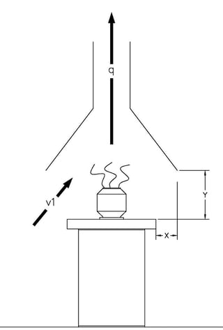
To gain good capture, the hood must be positioned as close to the source as possible without impeding access to the source.
Overall control is defined as the percent capture (or removal [R]) multiplied by the percent control (or destruction [D] if a thermal oxidizer is used), and divided by one hundred. Thus, in the illustration above, if the VOC capture efficiency is determined to be 70% and the control efficiency of the thermal oxidizer is determined to be 95%, the overall control efficiency (or DRE) is (70 x 95)/100 = 66.5%.
Because a well-built thermal oxidizer typically destroys more than 98% of all VOCs, fugitive emissions are often the single biggest contributor to overall VOC emission rates. Fugitive VOC emissions can be either eliminated by effective design of either Close Capture Hooding or a Permanent Total Enclosure (PTE). In either case, rigorous USEPA test methods are used to demonstrate VOC capture efficiency.
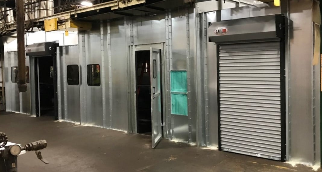
Permanent Total Enclosure (PTE)
What are Permanent Total Enclosures?
A Permanent Total Enclosure (PTE) is just what it sounds like: a fixed installation that contains all of the VOC emissions so they can be collected and directed to a control device (such as a Thermal Oxidizer [TO], Regenerative Thermal Oxidizer [RTO], or Catalytic Oxidizer [CatOx]).
- A total enclosure is a permanent containment structure, completely enclosed with a floor, walls, and a roof to prevent exposure to the elements, (e.g., precipitation, wind, and runoff), with limited openings to allow access and egress for people and vehicles, that is free of breaks, cracks, gaps, or deterioration that could cause or result in fugitive metal dust.
- A total enclosure with negative air that is vented to pollution control equipment is a total enclosure with negative airflow. This total enclosure must meet the industrial ventilation guidelines at each opening and the air within the enclosure is vented to an air pollution control device.
 The design criteria for a PTE are set forth in EPA Method 204. There are five requirements:
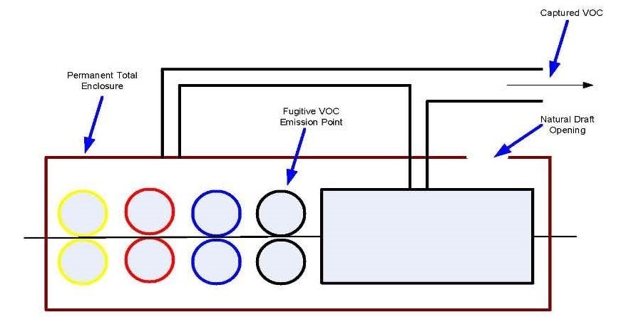
- The total surface area of the Natural Draft Openings (NDOs) into the enclosure cannot exceed five percent of the total surface area of the PTE. The surface area of the PTE is defined as the combined area of all walls, ceilings, and floors of the PTE. A NDO is any opening that is permanently kept open to allow for air flow into or out of the PTE. Access doors that are normally closed do NOT count as a NDO.
- The distance between the fugitive VOC emission point nearest to each NDO must be at least four NDO diameters in length. For example, if a NDO has a diameter of two feet, the nearest fugitive VOC emission point must be at least eight feet away.
- The distance between the capture hood or duct opening nearest to each NDO must be at least four duct diameters away.
- The average face velocity at each NDO must be at least 200 feet per minute, and the air must flow into the enclosure at each NDO.
- Any doors or access panels that are not counted as NDOs must remain shut during normal operation of the emissions-generating unit.
 In addition to the EPA design criteria described above, a PTE should be designed to minimize worker exposure to VOC fumes if they are going to regularly work within the enclosure. If workers are to gain access for any reason into a PTE, then the designer must account for worker exposure limits. Each solvent type has a Permissible Exposure Limit (PEL) that should be considered in the design strategy.
For example, if toluene is emitted from a process, the exhaust rate of the enclosure should be designed with sufficient air turnover such that the OSHA PEL of 200 PPMv of toluene will not be exceeded. When planning to build a PTE, the enclosure will first be designed to ensure that it meets EPA requirements (as described in items 1-5 above). Then, worst-case (maximum emission rate) conditions are considered, and the expected concentrations of individual compounds within the enclosure are calculated. If a comparison of these concentrations to OSHA PELs shows that one or more PELs may be exceeded, the PTE may need to be redesigned and/or exhaust rates may need to be increased.
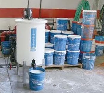 |
A PTE can be designed to contain fugitive emissions from a storage and mixing operation. |
Here are a few tips when considering using a PTE:
- Enclose only what is necessary to meet design criteria.
- Follow good engineering practices - Consider access and workability.
- Seal all connections between the oven (or other sources of VOC emissions) and the enclosure.
- Do not underestimate the need for complete access for cleaning, make-ready, and equipment repairs - Time and labor to dismantle an enclosure is costly and takes away from production time.
- Use wire-reinforced glass or solvent resistant plastic for visual inspection areas - Safe and long-lasting windows resistant to damaging solvent vapors provide a longer, more useful life for the PTE.
- Whenever possible, use the oven, coater, or equipment as an exhausting mechanism. Try to eliminate fugitive blowers ducted directly to the control device - This simple technique lowers the air volume at the oxidizer for reduced overall costs.
- Get operator and maintenance input in design stages prior to implementation - Let the employee feel as if they designed the enclosure system, which encourages continued use after the initial installation.
- Consider electrical hazard ratings for instruments and electrical devices within an enclosure - Codes may dictate Class 1, Zone 1, or 11 ratings. The exact electrical requirements are based on the design details of the PTE.
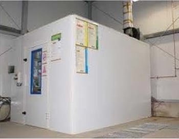
Temporary Total Enclosure (TTE)
What is a Temporary Total Enclosure?
A Temporary Total Enclosure (TTE) is, as the name implies, a temporary installation that is used for testing purposes only. The purpose of a TTE is to collect fugitive VOC emissions that would ordinarily be emitted into ambient air. This could happen by emissions escaping through doors and windows in the plant, or by passing through the facility’s HVAC system. A TTE allows an emissions testing firm to quantify these fugitive emissions.
TTEs usually come in one of two types:
- A truly temporary structure is built around the emission unit to be tested. This type of TTE very often consists of frames made with lumber and covered in a plastic material, such as a sheet of the polyethylene material Visqueen.
- A building or room can be designed to act as a TTE, under the “Building Enclosure” option. In these cases, normally open doors may be closed, passageways temporarily sealed with tarps, and/or HVAC systems turned off for the duration of the test period. As is the case with PTEs, the EPA has strict design criteria for TTEs.
The tests performed with a TTE to determine capture efficiency are long and, relative to other types of emissions tests, expensive. A typical TTE test involves at least four 10-hour days of work. During this time, a testing company is required to conduct three eight-hour capture test runs, in addition to other, less time-consuming tests to support the main effort. A TTE test can also be very disruptive to production, although usually much less so when the “Building Enclosure” option is chosen.
Given the time, expense, and disruption involved in testing for fugitive VOC emissions using a TTE, operators are well advised to ensure that their local capture systems are performing at optimum efficiency and meet all applicable regulatory and permit requirements before formal testing begins. For most processes, it is possible to accurately determine VOC capture efficiencies using information measurements before the formal emission test begins, at a fraction of the cost of formal testing. Typically, information measurements are conducted by comparing VOC usage rates to the VOC emission rates within the ductwork leading to the control device. Face velocities at hoods and other collection points can be measured using anemometers, pitot tubes, smoke tubes, and other techniques.
If you are considering using a TTE, here are some tips to follow:
- Use this approach to avoid improperly sized rooms: Too big = too much air = excessive compliance costs.
- Rooms with specific traffic patterns may not be capable of meeting requirements when considering routine operation. Buildings with low negative pressure may be too costly when air make up systems are factored in, and the overall cost may be higher than that of a well-designed PTE.
- Make sure to seal all windows, doors, roof vents, etc. Even room to room ventilation systems will need modifications.
- Consider installing close capture hooding to improve the room environment. OSHA guidelines for room ventilation and air changes will apply. Get operator and maintenance input in design stages prior to implementation.
- Make sure all processes are balanced. Designing a capture system for an unbalanced process can be costly and inefficient.
We are happy to answer any questions you may have in the meantime; please contact us.

At Catalytic Products International, we work to make sure that our customers have the best solutions to their air pollution remediation needs and that they have the knowledge to continue to meet these needs as they grow and change. For more examples of how our expertise helps our clients find success, please read our Customer Testimonials.


