In our previous post we discussed what air pollution is and why anyone may need a Regenerative Thermal Oxidizer (RTO). In this post we explore more details about various RTO designs and describe the operating principles.
Regenerative Thermal Oxidizers are available in two-can, three-can, and multiple-can orientations, and all are custom engineered to your exact needs.
 2-bed RTO designs are the most common in current system designs. When used in conjunction with a well designed poppet valve, the 2-chamber ceramic media bed design systems are compact and highly efficient.
- 3-bed or multiple beds: Early generation RTOs incorporated 3-media beds or more. The number of media beds is based on the total exhaust volume the RTO is designed to treat. Single RTOs can be designed to treat very large exhaust volumes (greater than 100,000 standard cubic feet per minute, or SCFM), but this requires 3, 5, or 7 can designs.
Each RTO system incorporates specialized ceramic media in the regenerator (heat transfer bed) to allow thermal rate efficiencies in excess of 95%. The RTO heat recovery media is the ceramic materials used to recover and exchange waste heat. There are several different media choices available, each offering slightly different thermodynamic properties or application design advantages:
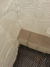 Structured Media: More common in modern RTO designs, structured ceramic media is geometrically designed to maximize surface area and minimize pressure loss. Structured media can easily achieve a 95% thermal rate efficiency in five-foot-deep bed designs, and can be increased to 97% with the addition of ceramic media.
- Monolith Media: Sometimes referred as honeycomb media, these monoliths are used in specialty applications.Random Media: The first generation of random media was golf-ball sized ceramic balls.
- Random media has evolved to incorporate specially designed ceramic saddles in an attempt to increase the available surface area of the media beds. Random media is typically lower in cost but not as thermally or pressure efficient as other choices. In addition, RTOs utilizing random media are usually physically larger.
There are several Regenerative Thermal Oxidizer RTO designs available today, and these are defined by the valves used to direct air flow throughout the system. These valves can include:
- Butterfly Valves: The first generation of valve design, commonly used in RTO designs that incorporate more than 3 regenerators (ceramic media beds). First-generation valves used hydraulic actuators, while current designs commonly use pneumatic actuators.
- Rotary Valves: Highly complex machined components are employed to provide the means of directing the exhaust through a series of multiple segments of a single media bed.
- Poppet Valves: Newer generation valve designs allow for fast actuation and tight sealing capabilities. Several designs include; one way, two way, vertical, or horizontal.
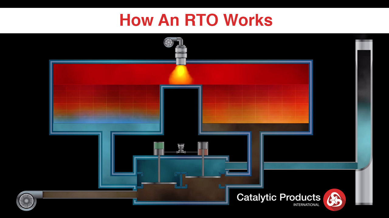
The Regenerative Thermal Oxidation process begins with the system’s programmable logic control PLC-based control system. The PLC controls will automatically energize the (1) booster fan, purge the system with fresh air, ignite the burner, and gradually bring the system up to the correct operating temperature. The PLC controls also monitor the temperature in the regenerators, combustion chamber, and valve assemblies. .jpg?width=426&name=How%20an%20RTO%20Works%20(no%20text).jpg)
As soon as the required operating temperature is reached, the PLC controls enable the process lines to feed into the oxidizer. A booster fan draws one or more VOC-laden exhausts from the process lines into the system. From there, VOCs are directed (2) into one of the system’s regenerators (an internally insulated vessel containing ceramic media). The contaminated gases are passed through the first regenerator, where energy is transferred from the ceramic media to the gas in order to elevate the temperature. The elevated temperature approaches the ignition level for most solvents and the contaminated stream is then directed from the ceramic bed into the combustion chamber. As the stream exits the ceramic bed and travels through the internally lined combustion chamber, minimal heat is added to ensure a proper oxidation temperature, and a designed dwell time is maintained for the ultimate destruction of the stream’s VOCs. The resultant clean, oxidized gases are redirected into a second regenerator bed to continue the energy transfer (3) and oxidation cycle before being released to atmosphere. This hot and clean air stream flows over the second regenerator bed and adsorbs the heat.
This process generally occurs over a three-minute time frame. Once the regenerator bed has absorbed sufficient heat (which takes about 3 minutes), the valves (4) will change position, and the cold VOC-laden process exhaust is re-directed toward the second hot ceramic regenerator where pre-heating will take place.
Along with the variety of RTO designs, there are a variety of add-on auxiliaries that can be employed based on the needs of the application. These can include:
- Hot Gas Bypass: A specially designed damper that is used to divert excess heat energy directly to the exhaust stack. A hot gas bypass is used when excessive VOC loads are processed in the oxidizer as a means of controlling operation and not shutting down on high temperature alarms.
- Natural Gas Injection (NGI): A means of adding auxiliary fuel (natural gas) when VOC loads are unusually low, or a means to assist with lowering the nitrogen oxide (NOx) byproducts of combustion.
- Low NOx Combustion Systems: Combustion of fuels such as natural gas or propane always results in combustion byproducts. Certain industrial burners are available that offer lower NOx byproducts and can be employed when local regulation requires.
- Bake Out: A means of controlling the RTO to force higher temperatures to the cold face area of the RTO. The cold face is the floor that supports the ceramic heat exchange media. In some applications, directing temperatures greater than 600° F to the cold face will remove organic condensates from the system – much like a self-cleaning oven.
- Forced Draft or Induced Draft Design: Forced draft consists of positioning the RTO main blower in front of the RTO or forcing the exhaust through the system. Induced draft consists of positioning the RTO main blower at the end of the system and drawing or inducing air flow through the system. The main advantage of induced draft is to protect the main blower from potential condensate buildup.
- Regenerative Catalytic Oxidizer (RCO): In certain applications, it may be economical to add sufficient catalyst to achieve a catalytic oxidation of the pollutants. This allows operation at much lower temperatures and reduces the cost of operation.
- VOC Polishing Chamber: A specially designed chamber that works with the RTO to help increase VOC removal efficiency. This can be an economical add-on compared to other RTO system designs.
This blog has explained the regenerative thermal oxidation process and a variety of designs and options. If you have any questions on which RTO design or add-ons are best for your needs please contact us. Also consider that Catalytic Oxidizers or Thermal Oxidizers may meet your specific needs and offer different operational advantages.
If you are looking for guidance or maintenance tips to keep your existing RTO up and running please contact CPI's service department to discuss your air pollution control device equipment needs.